Having the right components in place is essential for getting a job done, and with many connector types available it’s important to know the distinctions between the various options.

Having the right components in place is essential for getting a job done, and with many connector types available it’s important to know the distinctions between the various options.
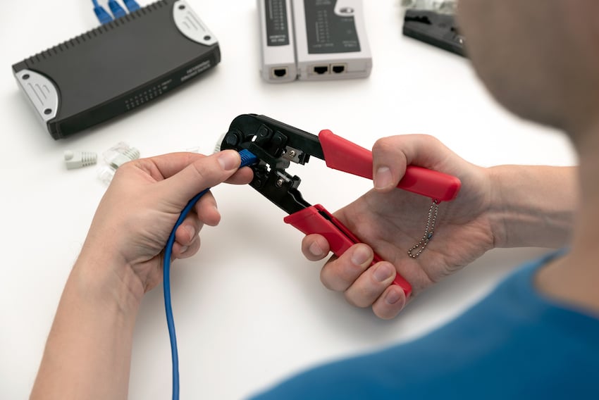
Electrical connectors are a type of hardware that affixes to a receptacle to complete an electrical circuit and deliver electricity to a piece of equipment. This connection can be between two wires or a wire to a terminal. Crimping is a process used to join wire to wire or wire to terminal. Just as the name suggests, bonding occurs when one piece of metal is deformed and compressed tightly with another piece of metal. This process does not require any soldering, and involves the following steps and equipment:
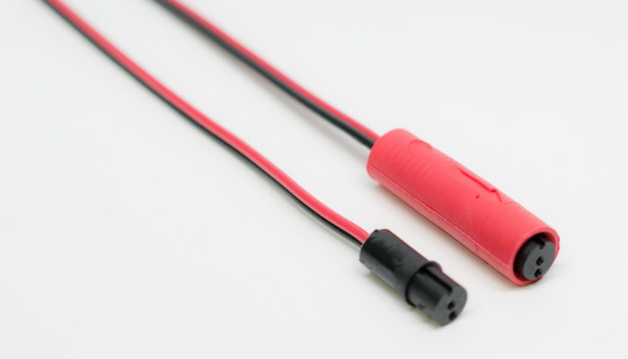
A top concern for shielded cable assemblies involved in the transmission of data are electromagnetic and radio-frequency interference (EMI/RFI). The slightest disturbance could decrease signal quality, cause data loss, or completely disrupt the signal, resulting in equipment failure.
Shielded cable assemblies feature shielding, which is a layer of insulation (containing electrical energy) that is wrapped around an electrical cable to prevent the cable from emitting or absorbing EMI/RFI. iCONN Systems specializes in various types of shielding, but the most commonly used methods include “foil shielding” and “braided shielding.” Here is a direct comparison of foil shield vs. braided shield to help you decide which is best for your product. Keep in mind, when you partner with iCONN, we will help guide you on every detail of your shielded cable assembly construction to ensure the right fit for your application.
An Ingress Protection (IP) rating is a measure of the degree of protection provided by an electrical connector against the ingress of solid particles and water. The ingress of solid particles and water can cause damage to equipment, potentially leading to malfunction or failure. By selecting electrical equipment with the appropriate IP rating or ‘code,’ you can ensure the equipment is able to withstand the conditions in which it will be used, minimizing the risk of damage or failure.
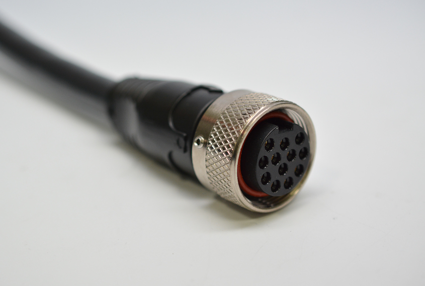
Few details will influence a product's success as significantly as its electrical design. Customers often need turnkey solutions that are both rugged and field-installable. While more affordable off-the-shelf connectors can meet a variety of application specifications, it's not uncommon for this combination of attributes to require customization, which may increase the upfront cost of ownership.
Custom circular connectors may cost more upfront but can significantly enhance lifespan, reliability and usability, making them more cost-effective. This article will help you understand your many options for power and data connectors and how specific design details can impact lead time, cost of ownership and ROI.

The global pandemic accelerated both the development and adoption of biotechnology — a field of research as impactful as it is controversial. Biotechnology trends are transforming modern medicine, enabling doctors to diagnose, treat and care for patients with greater speed, safety and effectiveness.
Here are the top trends with the greatest potential to reshape the patient experience and the future of healthcare.
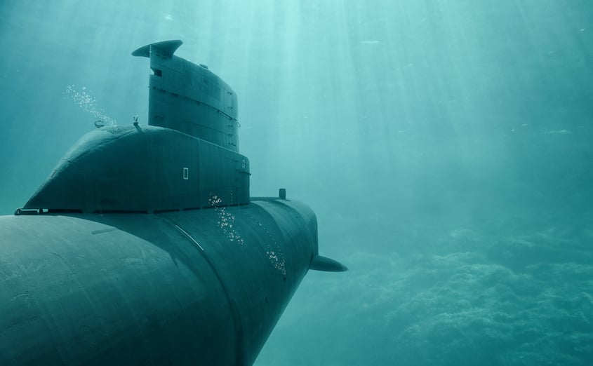
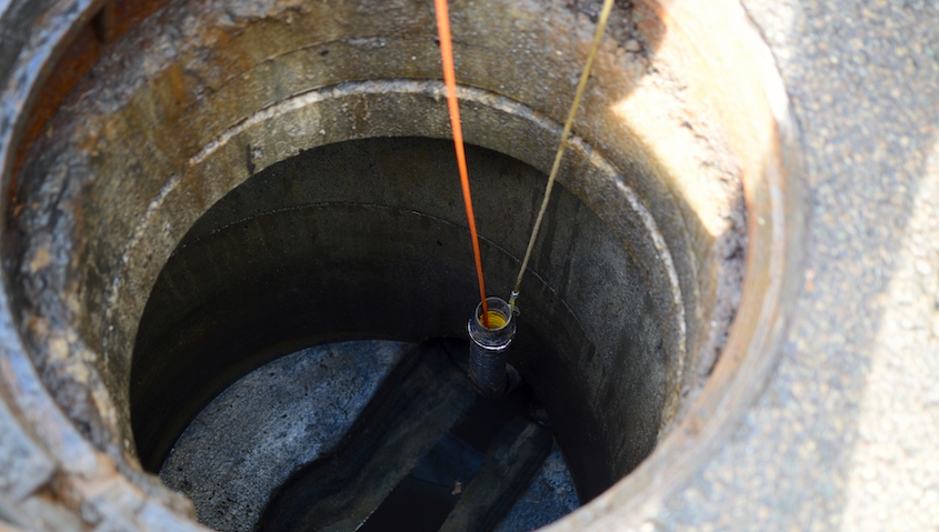
Between the sheer inaccessibility of the deep sea and its many dangers for a human operator, underwater environments represent the perfect testing ground for autonomous vehicle technology. One of the greatest challenges engineers have faced in this endeavor involves the volatile relationship between electrical components and water. Sophisticated machines require a sophisticated power supply that neither limits exploration nor puts technicians and equipment at risk. To fully understand this sentiment, it’s important to recognize the amazing innovations in unmanned underwater vehicles (UUV) and the industrial applications driving the need for more reliable electrical connectivity.
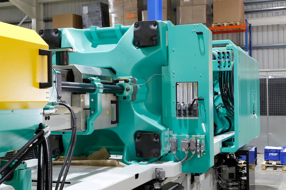
If you’re considering injection molding services, you’re already aware that this process allows design teams to achieve greater specificity at higher volumes. What you might not realize are the advantages of choosing to work with a service provider versus producing injection molded parts in-house. Here’s what you need to know.
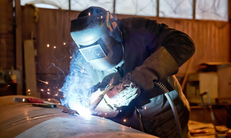
Soldering is a technique used to affix two metal surfaces mechanically and electrically — for example, flex circuits (also referred to as printed circuit boards (PCBs) and electrical connectors. The process involves a metallic material called solder and a heat source (selective solder equipment) to melt the solder, thus creating a joint between the two metal parts.
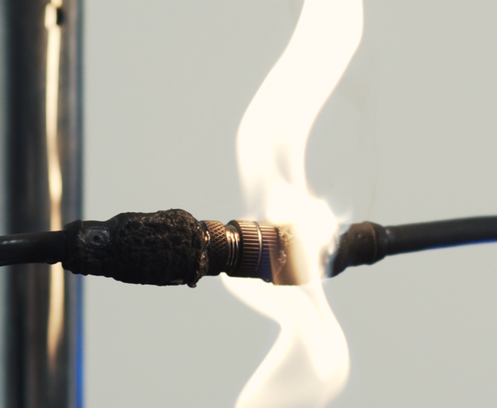
At iCONN Systems, we combine advanced rapid prototyping technology with a maverick team of design and manufacturing engineers to overcome the most extreme environments on the planet, including applications that involve direct exposure to flames and temperatures as high as 260⁰C (500⁰F). Let’s take a closer look at how we carefully select materials for molded cable assemblies in high-temperature applications (environments that exceed 60⁰C (140⁰F). Bring on the heat!


